Sunday, December 27, 2020

Project-Zero: End of December Update

It's been a minute since my last update.  Haven't gotten a ton more progress in but there are a few updates.

Driveshaft/Differential

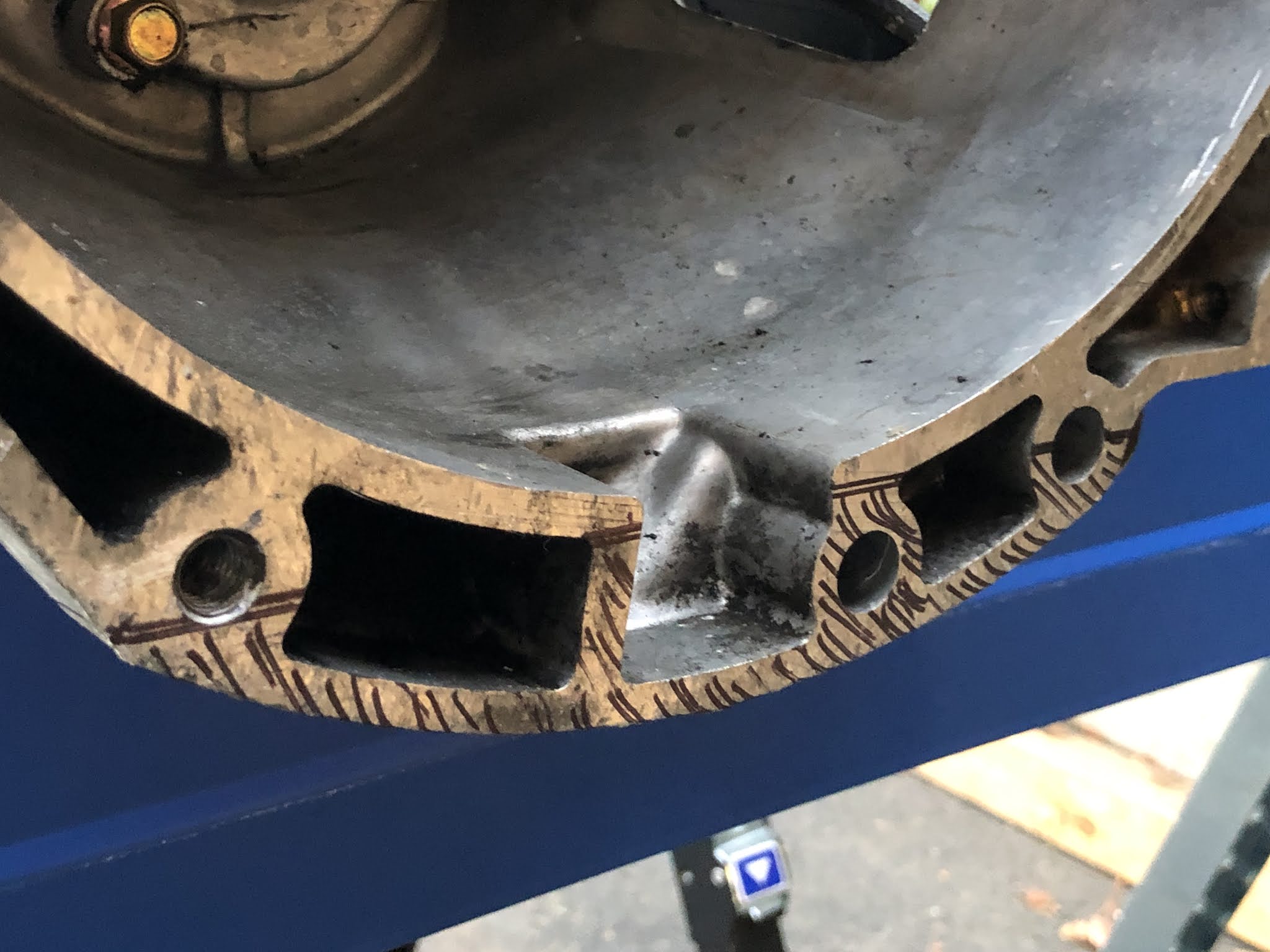
The drive shaft is installed and fits perfectly. Discovered that the bolt pattern on the diff flange isn't square, small pain in the ass. Unfortunately I'm going to have drop the diff at least once more to sort out some bushing issues.  Future me issue, though.

Short Shifter

The lower ball bushing provided by GBS is too big for the NC 5-speed transmission. Needs to be replaced with a slightly smaller bushing for 1990-2014 5-Speeds. I've ordered a new bronze bushing from 5X Racing...because why order a cheap-o plastic bushing when you get a trick machines bronze bushing instead?

When tightened down to the correct torque, the shifter ball binds up making shifting impossible. The difference between binding a moving smoothly is just a couple of lb/ft of torque on the screws. A compressible shim made of FelPro 3060 1/32" (.03125"/.79mm) fiber-rubber gasket material should fix that.

Windshield

Installed but I cracked the glass in the process, all of the local autoglass shops I've called have laid off their custom glass guys due to the downturn in business in the Virus Timeline. I'm punting this down the road to be a problem for FutureMe.

ITBS!

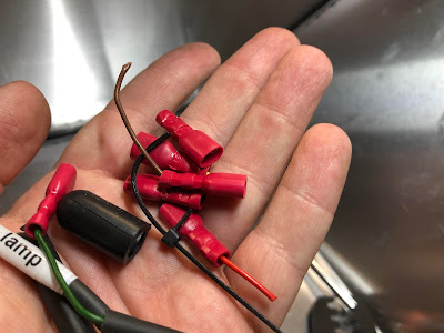
The Individual throttle bodies are are now permanently bolted to the car without any dramas. One of the header bolts is super short, I ordered a 50-pack of M8x1.25x12mm socket head screws from McMaster-Carr. It would have been really nice if GBS had machined the throttle body flange to accept the OEM Ford O-rings.

Part of fitting up the throttle bodies included plumbing up the high pressure fuel system. I found that, again, PastMe did me a solid by ordering a crap-ton of fuel injection clamps.  Go me!

Header Installation

I've gotten a little further on that test fitting the header, it's pretty much bolted to the car forever, now. PastMe did PresentMe a solid, preemptively ordering M10x1.5x22mm flange head bolts last month that thread into the head smoothly. I think the issues had was due to the aluminum coating on the bolts I'd done the test fit up with.


The silence is also now installed on the car. I needed to shorten the header's outlet pipe by about an inch to get the silencer to fit. There's a chance that I'll need to trim it up just a little more but for now it's good!

Engine Harness

Laying out the engine harness things pretty much line up where they should but there are some small issues to work out.


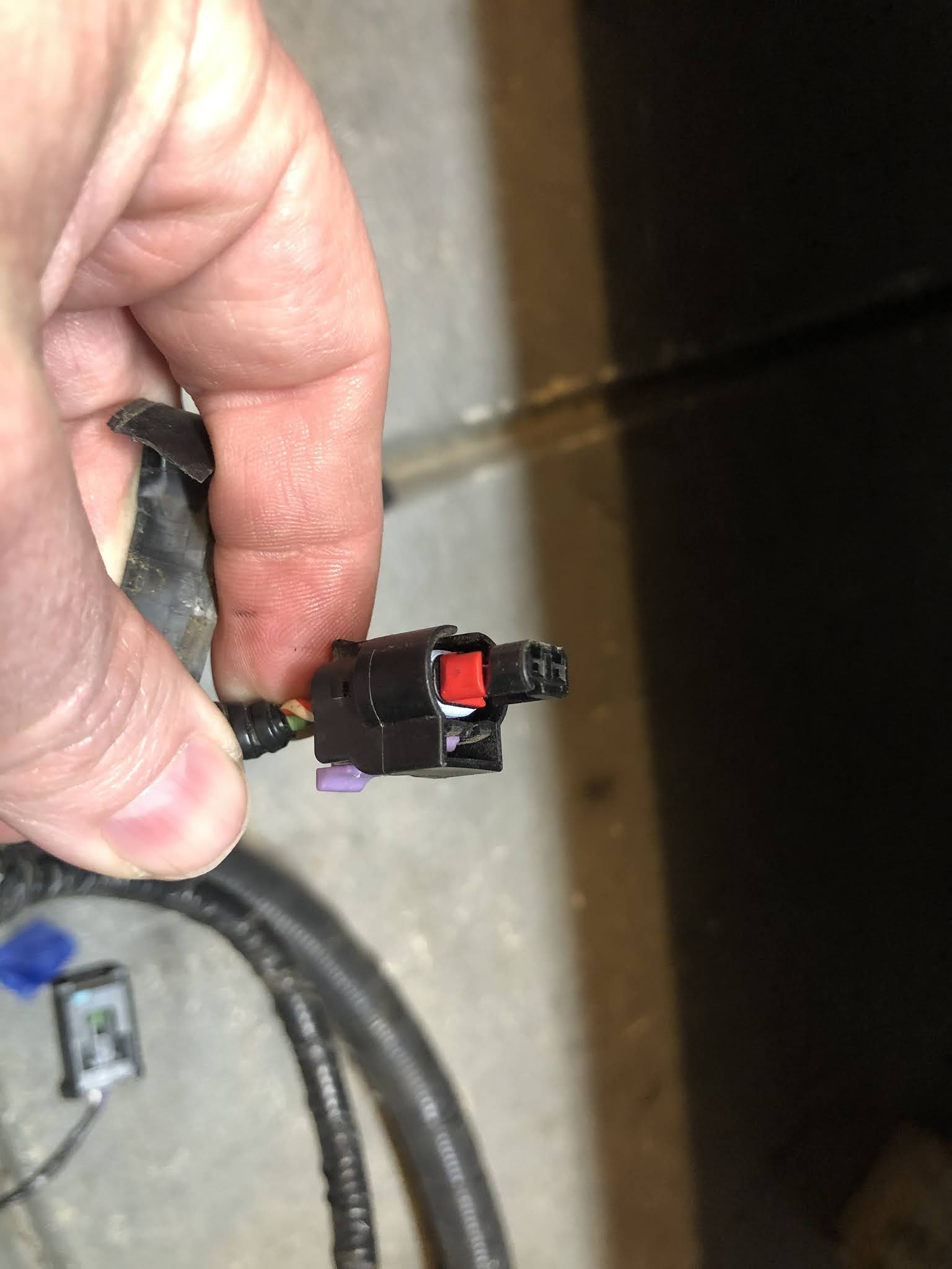
The 2.5L engine that I have came with a three-pin cam position sensor, the Emerald ECU and engine harness are setup for a two-pin sensor. Sourcing the correct sensor (DENSO 1966020) is the easy button fix. Snapped up the matching connector as well just to make sure I've got the correct harness connector for the sensor.


The harness also has a two-pin Deutch DTM connector for the VVT solenoid that's 100% incompatible with solenoid on my 2.5L. Fortunately I've kept the original engine harness so I'd have any odd-ball connectors on hand for situations just like this. I can either splice the OEM connector onto the Emerald/GBS harness or build a small patch harness.


Parts In Flight

There are a bunch of parts that are currently in flight for my build.

From GBS I'm still waiting for the left hand drive alternator bracket and parts, oil filler cap kit, and water pump inlet. All of these parts have been shipped but it took a ton of time for them to get here. It took a long time to get the bracket, GBS had to source ethical free-range aluminum from which to machine the part and then send it out to a small batch artisanal powder coater for finishing.

From Summit Racing I'm waiting on some SAE J30R7 hose, clamps, barbs, and sensors. The hose clamps and barbs are for the PCV/valve cover breather/catch can setup. The O2 sensor is just a generic heated four-wire unit that should place well with the Emerald K6 ECU.

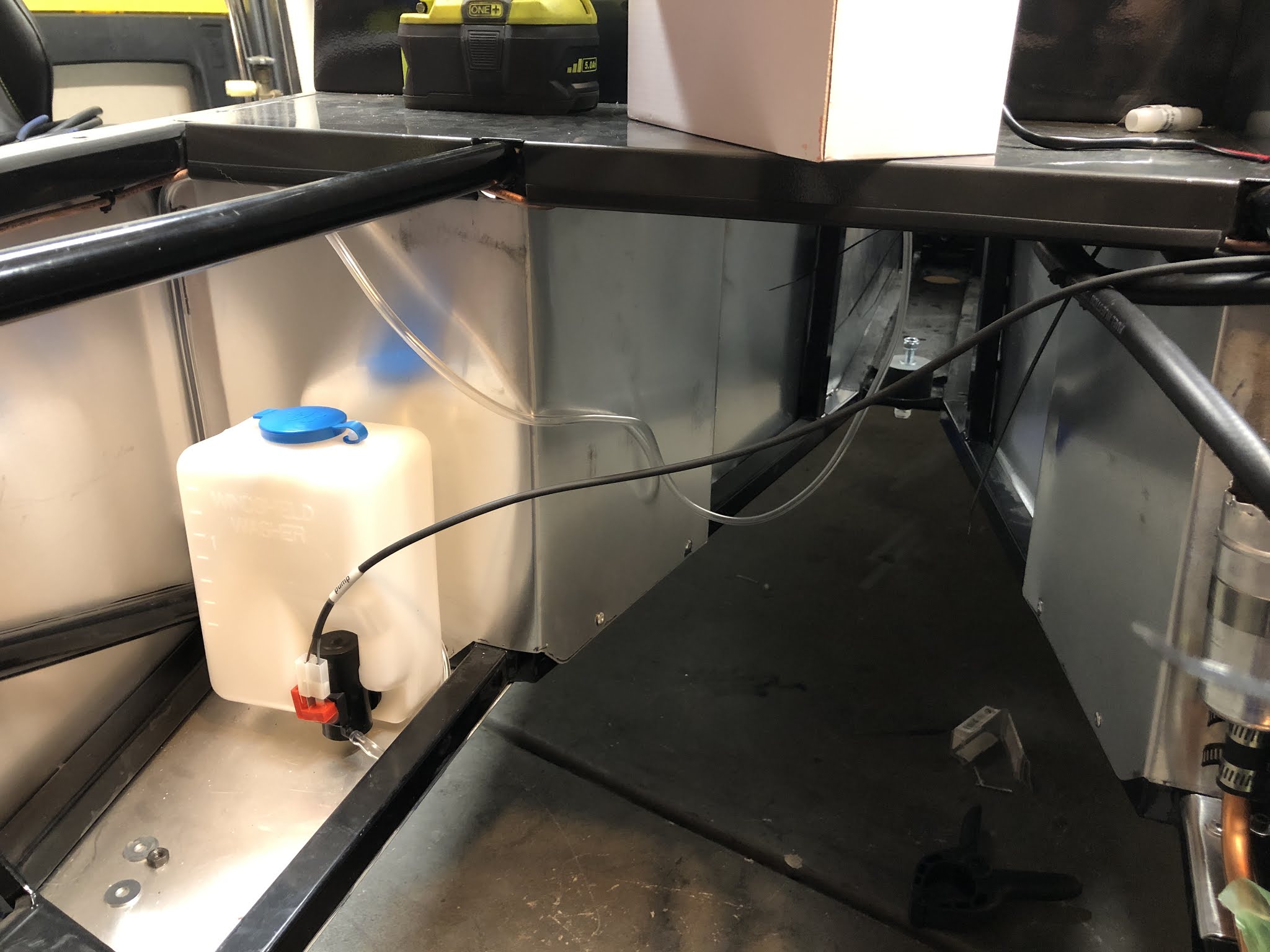
Over on the Amazon side of the equation I'm waiting for some more hose and a couple of 12mm check valves. The hose is 8mm clear silicone tubing to plumb up the expansion tank. The check valves are are to splice in-line with valve cover breather.

Monday, November 30, 2020

Project-Zero: Cultch Hosed.

After fitting up the clutch slave cylinder (CSC) I found that the clutch hose included in my kit was incorrect. The CSC has an M10x1.0 banjo fitting, the Girling-style clutch master cylinder (CMC) included in my kit has an 3/8-24 fitting. The host that GBS sent me has an M10 banjo and M10 male threaded fitting.

I've ordered a replacement hose from Pegasus Racing:
  • Braided 40" 3AN hose
  • 3AN straight swivel fitting for the CMC side.
  • 3/8-24 to 3AN banjo for the CMC side
  • 90˚ M10 banjo fitting for the CSC side.
Yes, I could work with GBS to get the hose replaced with the correct piece but I don't want to wait a month to get it.

Monday, November 23, 2020

Project-Zero: Header installed.

The engine is now more-or-less in.  Had to pull it out to clearance the transmission case a little more. With the help of a friend the job went surprisingly quickly.  After we had the engine back in, we threw the header on the car just makes sure the engine was sitting in a sweet spot.

Notes on the header: The 2.5L Duratec uses M10x1.50 studs/bolts for the exhaust manifold. Due to corrosion or residue from thread locker the threads might be a bit too tight to hand thread bolts in very far. I found that if I used a wrench, went slow, and used feel to know when to back off things generally be alright.

Ideally the head should be installed with studs.

I'll have a longer post about my thoughts on Duratec installation in a left hand drive GBS Zero chassis soon.


Sunday, November 15, 2020

Project-Zero: Oil pan fittings.

The oil pan has several ports in it, three (3) M12x1.5 ports and one (1) 1/8-27 NPT.

Two of the M12 ports are in the lower, front portion of the pan on the left and right as drain plugs.  The last of the M12 ports at the upper side of the left side of the pan for a dipstick tube.  The 1/8-27 port is near the bottom of the pan below the dipstick tube.

Due to clearance issues, I’m going to use the right-side M12 as the primary drain-plug for the car.  I’ve put plugs in the remaining two M12 ports. (My Duratec has its dipstick tube located through the head/valve cover.) I’ve also installed a plug in the 1/8-27 port since the clearance there is too tight for a temperature sensor.

Project-Zero: Engine fitment issues.

 After installing the engine into the car, I’ve attempted to fit the alternator with the mounting kit supplied by GBS but ran into the usual snag that I was shipped the wrong parts for my application.

To make a long story short in two bullet points:

  • GBS shipped me an alternator kit for a right hand drive Zero Roadster, my Zero Roadster is left hand drive.
  • The RHD mounting kit places the alternator EXACTLY where the steering shaft for the LHD zero runs from the column to the steering rack.
I’ve emailed GBS about the issue, hopefully they’ll help me correct the issue quickly. (i.e. ship me the correct alternator mounting kit ASAP.)

Project-Zero: Further transmission mods required

After installing the engine/transmission I found that one of the flanges I'd had to cut off the transmission case hadn't been trimmed enough.  In the photo below you can see where it is contacting the chassis.


It took a week to wrangle up the help of a friend to pull whole package back out and grind out some clearance.

GBS don't really provide any kind of template for just how much you need to remove/grind away from the transmission case for fitment.


Friday, November 13, 2020

Project-Zero: Transmission Mods

 To stuff the engine and transmission package into the GBS some trimming needs to happen.  Specifically, few mounting tabs and part of the bell housing have to go away.  This is particular to the Ford Duratec to NC Miata/MX-5 gear boxes.

On stock cars with stock oil pans the lower bell housing bolts thread into the pan. When using a low-profile sump the lip of the bell housing extends lower than the oil sump by about an inch and a half.  Best just to trim it off rather than catch a rock or a curb

This is a view of my friend’s transmission without the bell housing trim.

The job is pretty straight forward, you just need to slice it off clean across the bottom just under the wall of the bell housing where it spiders out into webbing for the bell housing’s flange.  A straight edge works great, a sharpie is good for marking out what you want to cut vs what you souls to cut.  Then it’s just a matter of going at it in bits and pieces with an angle grinder.  It took a bit of work and swearing to make it happen but it happened.


Wednesday, November 11, 2020

Project-Zero: Flywheel and clutch installation

 This evening after work I knocked out installation of the flywheel, clutch, and starter motor.

Clutch and Flywheel

The clutch and flywheel installation were pretty straight forward. The flywheel is an 11lb unit I sourced on eBay, the clutch is a Flyin’ Miata level 1 NC 5-speed clutch. I opted to upgrade to ARP flywheel and clutch clover bolts for the installation, which I sourced from Massive Speed Systems.

ARP’s installation instructions for their flywheel bolts differ from the factory service manual.
  • Apply the included ARP lubricant to the bottoms surfaces for the flywheel bolt heads. A little bit will go a long way.
  • Apply LocTite 242 to the threads of the flywheel bolts, then install the flywheel and bolts.
  • Following a star pattern, torque the flywheel bolts to the final torque value of 95lb/ft while keeping the engine/crank from rotating.
ARP offered not instructions for the pressure plate bolts however they did include a small sample of red LocTite with the bolt kit.  I have opted to use blue LocTite gel, approximately the same strength as LocTite 242.  All pressure plate bolts were torqued to 38 lb/ft per the Haynes MX-5 workshop manual.

Fresh pilot bearing was installed using a 19mm socket and impact extension.


Starter Motor

Back in July I bought an NC 5=speed starter motor from a Miata breaker in Texas for the whopping sum of $55. It came out of a car with somewhere in the neighborhood of one hundred and twenty thousand miles.  Installation was smooth and easy.  I used socket cap head screws, torqued down to 38lb/ft

Sunday, November 8, 2020

General-Shop: Torque Adapters

 Today I'm reminded that, sometimes, it's hard to get some fasteners to properly torque them down without some kind of adapter or lever.  The problem is that when you add an adapter/lever to reach a hard to get to fastener you change the lever length of the torque wrench and thus change/increase the amount of torque that's being applied, sometimes by a lot.  Fortunately there's math for that.

In the most simple application where we have to extend the total arm length we have to reduce the amount of torque applied the formula looks like this:

R = L * T / L + A

  • R = The reduced torque
  • L = The length of the torque wrench from the center of the head to the center of the grip.
  • T = The initial torque required.
  • A = The length of the adapter between the center of adapter heads.

In this case, I need to tighten a water neck bolt that's blocked by the water neck so I'm using a 10mm box end wrench as torque adapter:

  • T = 93 in/lbs
  • L = 240mm
  • A = 120mm

When you boil this down you get the following:

  1. R = 240 * 93 / 240 + 120
  2. R = 22320 / 360
  3. R = 62 in/lbs 

For a more torque adapter formulas, go here:

http://www.fordservicecontent.com/renderers/torquewrench/wrench_formula_main_en.asp

Side Note: The specified torque value for the thermostat housing/water neck on the 2.5L Ford Duratec is 89 in/lbs (7.1 lb/ft), I'm going with the higher generalized torque value of 91 in/lbs (7.6 lb/ft) because .5 lb/ft difference is effectively a rounding error.

Friday, November 6, 2020

Project-Zero: Oil pickup tube install

 Been a while Stuff has happened.

GBS shipped me a now oil pickup, it arrived this week after what felt like an eternity so that’s now installed. The oil pain and oil filter housing are also now installed on the engine.

The pickup requires an o-ring seal, the original Ford o-ring seal does not fit in this application. (GBS machine the mating flanges, they could make it use the Ford o-ring if they wanted.) I think the most correct size is a Dash 022 o-ring but in a pinch a 1.0625” inside diameter ring will also work.

Cap screws get a dab of blue thread locker to make sure they don’t back out  and are torqued to as close to spec as possible.


The pan and oil filter housing go back onto the engine after cleaning up the mating surfaces. Carefully scraped them down with a razor blade, then wiped them with acetone. Black RTV applied per the tube instructions to seal the pan  and filter housing. Final torque per Ford Fusion Haynes manual.


Wednesday, October 28, 2020

Project-Zero: Dealing with crappy spade terminals.

 In the process of fitting the chassis harness to the car, I've run into issues with of the crimped spade terminal slipping off the wires while handling them. The issue is entirely with the style of insulated crimp terminal that whomever built the harness used. In my experience this style of terminal is just unreliable: it's impossible to know if you've gotten a good, positive crimp on the conductor and sleeve. I've had more of these slip off of wires than I care to try to remember, including the two from last night. 


Sunday, October 25, 2020

Project-Zero: Spacers

 I've replaced the stacks of washers spacing out the differential with spacers sliced off a length of stock purchased from McMaster-Carr.  Would have been better on a lathe but the bandsaw wasn't a bad second choice. The stock came from McMaster-Carr, 1" OD aluminum tube. (1/4" wall).  Each spacer is ~14.5mm thick.


Tuesday, October 20, 2020

Project-Zero: 2.5L Duratec balance shaft delete

Why do this?

  1. The ATR low profile oil sump won't fit on the engine with balance shaft assembly in place.
  2. The balance shaft assembly weighs 20lbs, removing it saves on over all weight and removes rotating mass allowing the engine to rev higher, faster.
  3. You might get a few horsepower back without the parasitic drag induced by balance shaft assembly.

Will this hurt the engine or lead to premature wear?

No.

What parts do you need?

You need a balance shaft delete kit.  In no particular order, pick your poison--they all work the same way.

How do you do it?

Removal is straight forward. Remove the oil pain to gain access to the balance shaft assembly. Four bolts hold the balance shaft to the bottom of the engine where it engages with the crankshaft via a large sprocket.  Wind out the four large bolts and the unit lifts out of place easily.


After removal, the oil galley that feeds high pressure oil to the balance shaft must be plugged using a delete kit.  Delete kits are inexpensive and available from a couple of different suppliers.

Kit installation is the same for all of them.
  • Lube the plug o-ring, then stick the plug in the oil galley.
  • Apply red loctite to the retaining bolt, install bolt and torque to spec. (18 lb/ft)


Reinstall the oil pan per factory service manual procedure.

Notes

  • I went with the Massive Speed Systems kit because I was also buying their lightweight under-drive water pump pulley anyway.
  • Don't be a dumbass like me, I didn't have the necessary oil pick-up tube handy to install the new ATR oil pan. Now I have to wait for parts for to be shipped back to me.


Thursday, October 15, 2020

Project-Zero: Update on some small jobs

  • Parking Brake Cable RoutingHaving taken a look at some of the photos from Richard's build, I now have a better idea of how the parking brake cables are supposed to be fitted into the chassis bracket.  This will be a quick and easy job.
  • Paint the swirl pot hard line - Unnecessary but a small touch that’s easy do now before the car is wet with fluids. Painting it is really just a aesthetic thing since I’ve also painted the swirl pot gloss black.
    • Quick and dirty operation, scrubbed down with steel wool, sprayed with one coat each of primer (heavy), base gloss black (medium), and gloss clear coat. (Heavy). No need to do multiple coats of each on this part.  Once it’s had a day or two to cure I’ll jam it back into place and clamp it in.


  • Washer ReservoirHaving taken a look at some of the photos from Richard's build, I now have a better idea of where the washer bottle is supposed to be mounted.
    • Fixed with M8 rivnuts and cap-head screws. This is overkill but it is what it is. The car was drill with 7/16" holes for the bottle mount.
    • The washer harness will need to be extended, the harness is configured for right-hand-drive but this is a left hand drive car.


  • Los Honry BoyHaving taken a loot at some of the photos from Richard's build, I have new ideas about where I might be able to install the horn that's mostly out of the way.
    • There’s a lot of dead space between the radiator and the front of the engine, I decided to mount the horn off one of the steering rack brackets.


  • Give em' the clampsI need to acquire more worm clamps of the correct sizes to finish up the high pressure fuel pump hard line installation.
    • Notes: I picked up some slight too large camps from OSH, they will work alright.
  • Tighten up the transmission mount bushing - I really don't need to put more explanation into this.
    • Notes:
      • Tighten to M10 Class 8.8 w/ thread locker torque spec
  • Route the electrical loom at the back of the car - This should probably go from the right side of the car to the left.
  • Dig Out the Transmission and 2.5L engine - We're getting to that point. I should start working on these. First task, pull them out of the corner of the garage and clean them up.

Tuesday, October 13, 2020

Project-Zero: Fuel Pump Specs

Noting down some information on the high pressure pump currently installed in my Zero.

Manufacture: Bosch
Manufacture Part Number: 0-580-464-015
Ford Part Number: EOVF-9350-AA (483180013)
Minimum Current: 12 Volts, Max Power 6.5 Amps
Operating Pressure: 43.5 PSI (3 Bar)
Minimum Flow @ Outlet: 34 GPH (130LPH)

https://drive.google.com/uc?export=view&id=1DJe_g1hq222_APSQnrJL-IXGRLUpOCas

These pumps were used in just about everything, most seem to have come with ring terminals instead of spades. This should be alright but if I need to bump up to a larger pump, going with surge tank with built-in pump is going to be the way to go.

Project-Zero: Swirlpot hardline

I ordered a tube bender from Amazon, within fifteen minutes of delivery this [finely crafted] bit of 1/2" copper tube was bent up and in place.


The bend radius is just about a perfect 180˚ shot from the swirl pot outlet to the pump with barely any deformation. I might throw an Adel clamp at it for safety but it doesn't rub or touch anything. It's a pretty tidy solution.

Copper tubing is easy to get in my area, sold in 10-20ft coils in every hardware store, some stores sell it by the foot. Work hardening and cracking from excessive flex or pressure cycles won't be an issue on the low pressure side of the system.

For reference, this is what it would look like on with rubber tubing. (And on a right hand drive car, mounted on the right side of the chassis.)

ProTip: Pipe is measured from the inside diameter, tube is measured from the outside diameter.

Monday, October 12, 2020

Project-Zero: High pressure pump installed.

Some video of the high pressure pump installation and cleanup of the low pressure feed and return lines. Nothing really to write home about except maybe for the 3D printed host management clamps and the hub centering rings. (Post about those earlier.)


With I had more time lapse to share. I recently picked up a new set of batteries for the Yi 4K camera I've switched to for time lapse work, those batteries have turned out to be garbage. This lead to the corruption/loss of the latest video file when the battery shit itself without warning. (The camera didn't have time safely close out the session before the battery said, "Not today, Satan!")

Tuesday, October 6, 2020

Project-Zero: 3D printed hub centering rings

The Short Story

After figuring out the bore and hub diameters, I printed hub centering rings for my car. They should be adequately durable if printed in ABS, ASA, or PETG with 100% infill.

I printed mine with Shaxon ABS at .28mm layer hight. Pumpkin orange. Because October.

Link to the parametric Thingiverse model I'm using: https://www.thingiverse.com/thing:40516

Link to the custom models I remixed from this: https://www.thingiverse.com/thing:4617312

Fin.

NOTE: I've since ordered a set of injection molded ABS plastic centering rings.


The Long Story

Needing to keep the wheels concentric to the spindles, hub centering rings are a requirement and my kit didn't come with them.  Some simple searches revealed the ring sizes I'd need aren't unobtainium but since the the car has two different center bores and hub diameters, one full set in each size are required if purchasing commercial sets.

Since I own a 3D printer I spent 5 minutes in Fusion360 modeling up two test rings to make sure I had my measurements correct before slapping down fat stacks of cash on commercial sets.

https://drive.google.com/uc?export=view&id=154_LWOIDDaEz332ogJVHU3EyXHu-Dm5i

https://drive.google.com/uc?export=view&id=1CWYMXljsrmbOQc0KSngbZX644kbCBVSi

https://drive.google.com/uc?export=view&id=1W9Jy84cdiB30CvW2nvEqOP7mESQJnfZ3

The front ring was spot-on. (54.1 ID, 57.1 OD) The rear ring was too tight on the inside diameter by exactly one perimeter shell. (~.08mm) I adjusted the model to an ID of 64.1mm (the next standard hub diameter up, also ~0.8mm wider) for a second test, which also fit spot-on.

And then I thought, "Other people have to have printed their own centering rings."

A subsequent search of Thingiverse turned up a better parametric model than what I'd crapped out as a test. There were some pretty good reviews, including form somebody who'd done a track day with a set printed in PLA without any negative effect from heat on the rings. Thus, I'm not bothering to buy them, I'm just going to print them. Because I have the technology.

Sunday, October 4, 2020

Project-Zero: Wheel & TireFitment

NOTICE: The information on this page is expressly for my particular GBS Zero Roadster build.  My car has a fairly wonky staggered setup with 15x7 (4x100 pattern) fronts and 15x8 (4x10⁸ pattern) rears. 

Car Mechanicals 

  • Front: Mazda, Miata ( 1999 - 2004 )
    • Stud Pattern: 4x100mm
    • Center bore: 54.1mm
  • Rear: Ford, Sierra (1982 - 1993)
    • Stud Pattern: 4x108mm
    • Center bore: 64.1

Current Fitment: Team Dynamics ProRace 1.2

  • Front
    • Size: 15x7
    • Pattern 4x100
    • Center Bore: 57.1mm
    • Offset: ET -15
    • Tire: Toyo Proxes R1R
      • 195/50R15
  • Rear
    • Size: 15x8
    • Pattern: 4x10⁸
    • Center Bore: 73.1mm
    • Offset: ET -27
    • Tires: Toyo Proxes R1R
      • 205/50R15
  • Required Center Rings
    • Front: 54.1(ID) to 57.1(OD)
    • Rear: 64.1 (ID) to 73.1(OD)

Resources

Good video explaining how to measure offset.


Saturday, October 3, 2020

Project-Zero: Swirl pot mounting and mods.

I have two concerns informing my swirl pot mount:
  • Ensure clearance between the steering column and fuel return hose.
  • Ensure clearance on the bulkhead to mount high-pressure fuel pumps.
I knocked this together with a sheet of 4"x10" 14ga aluminum. Not necessarily ideal for every build but workable for mine. A minor, pretty straight forward modification of the swirl pot was base is necessary


Wednesday, September 30, 2020

Project-Zero: Rear Brakes, first fitment notes.

I’ve been looking over Richard’s build log for some information on mounting the Sierra brake calipers, having one of those moments where I can only think, man, that just can’t be right? Specifically swapping the calipers left for right. I’m not saying that it isn’t the way GBS intend them to be mounted, just that it's weird because it would make servicing the rear brakes kind of a pain.  Having to dismount the rear calipers to bleed them is super sub-optimal.

UPDATE: 

After a little experimentation I've confirmed that you can't route the parking brake cables to the calipers if they're on the "correct" sides of the car. Disappointing but whatever...Might be a reason to upgrade to different calipers later.

NOTES:

  • Caliper brackets bolt to the uprights with M10x1.5 50mm bolts.
  • Parking brake cables are 10mm (3/8") diameter, good to know for replacing the p-clamps.

Sunday, September 27, 2020

Project-Zero: Rear end test fitments.

Decided t throw the differential and drive shafts into the car.  They’re needed to be able to install the rear brake hubs, rotors and brakes.

  • Off-the-shelf spacers suck - The spacers I bought from McMaster-Carr (M12x15mm) are just a bit too long. They bind up when attempting to install the differential.  I had been packing out the space with M12 washers. I was stupid and should have just bought a 2ft section of  1” OD .25” wall aluminum tube and ripped it down to size with the bandsaw.
  • Hub orientation - The hubs carriers have a flat spot on along one edge.  They should go toward the back of the car.
  • The axels are handed - The longer of the two axels goes on the passenger side of the car.  The axel nuts are left hand thread on the left side of the car and right hand thread on the right side of the car.
  • I need to clean the internal splines on the hub - They’re rough and do not slide nicely onto the axel splines.  I should scrub them out with some soft of steel/brass brush to clean up any surface rust and shit.
  • Once installed, the hubs and axels will install and remove as one piece, until then...it’s going to be a shit show.
  • The axel nuts require a 41mm Socket - I have ordered a 41mm deep impact socket. A1-5/8" socket would also work.
  • Once the hubs go on, they're staying on - Because the GBS kit does not use stub-axles once the hubs are on, removing the axle shafts becomes a HUGE pain directly in the ass for serviceability.


This is where I realized that the axels are slightly different lengths.

Hub carrier and brake caliper bracket installed.

Saturday, September 26, 2020

Project-Zero: Right rear upper control arm.

It’s only been a FUCKING MONTH since I found out that the right, rear upper control arm on my GBS Zero kit was in no way going to line up and go into it’s home...but it’s on the goddamn car now an barring something really fucky happening it’s not going to have to come off ever again.


It took most of the day to wrestle it onto the car, including a protracted run to the hardware store to pickup up some new, shorter M10x1.50x60 bolts for the upper and lower shock bolts. (For both sides of the car.) The hardware that GBS ships with their ATR shocks is M10.x1.50x70...and those are too long. On the upper mounts they interfere with the frame so you’re not actually able to tight them down snugly.  On the bottom mounts the excessive length isn’t such a problem but since I’m replacing some I might as well replace them all.

My only significant frustrations in this build [so far] have been the horrible quality of the front brake tube nuts and working with GBS to sort out the rear control arm issue. Getting GBS on the phone to talk through the issue was practically impossible. Ultimately the issue was sorted out in a few quick emails but my experience has been that it is almost impossible to get phone support from GBS. (From the US, at least.) I’m honestly deeply disappointed that it took nearly a month to get the control arm issue sorted out. It put a damper on my build enthusiasm with back-of-my head concern that potentially the frame might have had issues.

Monday, September 21, 2020

Project-Zero: Low Pressure Fuel System Plumbing


Started Plumbing the low pressure fuel system.

The feed fuel feel and return lines are 5/16” OD nylon tube in red and black. (red=feed, black=return.) These run from the low pressure filter and pump at the rear of the chassis through the tunnel to swirl pot at the front of the car.  The tunnel has some brackets to help route them cleanly.

The tunnel brackets need to be fitted with grommets to the fuel hoses from rubbing  through. I bought out all of the [5/16”ID, 716” groove diameter, 1/16” groove depth] grommets at my local Outdoor Supply Hardware. These fit into the brackets perfectly and offered a VERY snug fit for the nylon lines.  So snug that nylon fuel lines tended to pull the grommets out of their home while drawing them through.

To solve this, I squeezed a nickel-sized gob of white grease onto a paper towel, then drew the full length of each tube through the greasy towel. I then wiped each tube down again with a clean, dry paper towel.  This left the nylon fuel hoses clean and just slick enough to thread through the tight rubber grommets without pulling out of the chassis in the process.


Thursday, September 17, 2020

Project-Zero: September Parts Drop

The only parts I planned to order this month have arrived.

  • Radium Engineering Ecoboost PCV kit
  • ARP flywheel bolts
  • ARP pressure plate bolts
  • Flyin' Miata clutch/pressure plate kit.
Of note, the Radium Engineering PCV kit is maybe a little unnecessary and overkill. The GBS comes with a PCV blanking plate for the Duratec/MZR engine that I've optioned for my car, it could be modified to suit.

Wednesday, September 16, 2020

Project-Zero: Ignition Barrel Replacement


GBS sent along a new ignition barrel to replace the one that came from the donor steering column. Replacing it is pretty easy if you have the original keys, I didn't.

Barrel removal if you have the original keys:
  1. Insert key into the ignition, turn to position "II".
  2. Press down on the small brass pin with a pick or a punch.
  3. Gently pull & wriggle the barrel out of the steering column.
Barrel removal if you don't have the original keys:
  1. Research "Tibbe lock picking" on Google, watch YouTube videos on the topic.
  2. Order a Tibbe lock picking tool and wait for it to arrive.
  3. Fail to pick the lock with the Tibbe lock picking tool.
  4. Drill out the brass pin with a 5/32" drill bit, then go to town with a hammer and screw driver.
Installing the new barrel:
  1. Insert key into the new barrel, align it so that the key is on "II".
  2. Insert the barrel into the steering column while pressing down on the brass pin.
  3. Have a cocktail.

Monday, September 14, 2020

Project-Zero: Sorting out diff mounting.


Some notes:
  • The installation Order of Operations for the diff are
    • Loosely install lower rear cross-bolt and spacers in the differential.
    • Lift differential in to cat nose/flange first, loosely bolt-in the nose.
    • Lift differential rear, insert the upper rear bolt.
    • Torque everything to spec.
  • Spacers are required:
    • After a little trial and error I found that I need 15mm spacers.

Project-Zero: Proportioning Valve Installed


Future proofing the build a little bit, I've installed a Wilwood proportioning valve between the master cylinder and the rear brakes. This will include a remote adjustment knob somewhere on the dashboard or center console.

In the process of installation I replaced the whole front-to-rear line which I'd completely mangled.  Made a small notch in a body panel for brake line clearance. Installed a 6" strip of clear door edge trim to keep from abrading the remote reservoir supply line to the master cylinder's rear circuit.

Friday, September 11, 2020

Project-Zero: Figured out what was wrong with the right rear suspension.

I've been having some issues getting the right rear suspension put together. The upper and lower control arms just wouldn't line up correctly with the upright. It was a very perplexing issue to encounter but it's getting sorted out now.

I after shooting photos back and forth with Richard at GBS we're pretty sure we know what's going on. First, there's nothing wrong with the mounts on the chassis. That's a huge relief. Second, there's nothing actually wrong with the dimensions of the upper control arm. It turns out I was sent two left upper arms, one of which has an incorrect shock mount bracket denoting it as a right side control arm.

GBS's Ford-style upper rear control arms are the same part left and right, just flipped over with a different shock mount bracket welded on; right-and arms have a notch on the shock mount. Flipping my right-hand arm over proved a notched bracket had been welded to an arm jigged up in left-hand orientation.

I've got a hypothesis for what happened. When GBS produced a set of Ford-style upper rear control arms, a notched shock mount was accidentally welded onto a left-hand arm. After powder coating, the arm was placed into inventory as a right-hand arm because of the notched bracket. It was just dumb luck that the wonky arm was pulled from inventory for my Zero kit.

I'll consider the issue closed as soon as I've got a new actual right-hand arm bolted up to the chassis. (GBS should be shipping it out to me on Monday.)

Wednesday, September 9, 2020

Project-Zero: Brakes, Differential Test Fitment


Brakes/Clutch Plumbing

The brakes and clutch use a common dual-outlet reservoir, which I kind of like. The front/rear brake circuits need to be plumbed into one of the outlets with a T or Y adapter, the clutch master cylinder requires a 7/16" to barb adapter and plumbs into the other reservoir outlet.

I've chosen to plumb the brakes to the side of the reservoir where the fluid level sensor is located.  I also decided that I wasn't happy with the routing required by the use of the GBS supplied 'Y' fitting so I bought a 5/16" nylon T fitting at OSH.

Presently waiting for a proportioning valve to arrive before I commit to remaking the rear brake line. More on that later.

Clutch Fitting

It's not easy finding a 7/16" UNF to 5/16" barb fitting, GBS supplied one in the inventory of parts for my car but I've misplaced it.  I sourced a replacement from Pegasus Racing. They also have a banjo style fitting that I may swap to if the vertical fitting doesn't work as well as I would like. (I don't think that'll be a problem, however.)

Differential

The differential is a 3.6:1 LSD from a Ford Sierra, it fits in the chassis well enough but I'm going to need to fabricate some spacers.  The mounts on the diff case are 7" wide, the chassis brackets are 8.25" wide.  This means I'm going to need 15.5-16mm spacers to center it up in the chassis mount.  I'm going to see if I can get away with printing them in ASA with 100% infill.

Project-Zero: Brake nuts, rear studs.


Front Brakes

I found that the threads of the tube nuts installed on the front brake lines at the GBS workshop were garbage, wouldn't thread on to the GBS supplied ATR braided flexible brake lines. Some other owners have run into the same issue, they've resolved it using an M10x1 tap to clean up the threads. I opted to replace the tube nuts, I was able to steal a good set from a friend's build. 

Rear Brakes

Rear brakes were zero dramas, everything there was fine.

Rear Hub Studs

With the use of a 20-ton press, I installed a set of ARP wheel studs in the Sierra rear hubs. I wanted to use ARP studs to match the style of studs in the front hubs. Turns out that ARP's NA/NB Miata/MX-5 extended wheels as almost a perfect, especially with the use of a 20-ton press.

Wednesday, September 2, 2020

Project-Zero: Steering column is in.

The steering column is in the car, for now. I don't think it's going to need to come out again any time soon. A bunch of tubes of torque seal arrive this week so hopefully I can start torquing things down this weekend.


The sierra column is, in theory, height adjustable but in application for this car might as well not be. In its highest possible position there's only a few millimeters of clearance between the triangular section of the steering column and one of the under-scuttle frame rails.

I've mounted the steering column in place with Class 12.9 M10x1.50x30mm (x2) socket head cap screws and Class 8.8 M10x1.50 nylock nuts.  To help spread out clamping force, I have used 30mm OD M10 washers on front face of the column mounting bracket. These fasteners are absolute over-kill and shouldn't be torqued to more than Class 8.8 M10 threadlock/lubricated spec.

The battery location is great! The Odyssey PC680 fits [almost] perfectly. This battery was damaged in shipping, a new one is on its way. Which reminds me, I should print some terminal protectors.

Monday, August 31, 2020

Project-Zero: Steering column hole.

Pre-fitment test of the steering column grommet and bushing show a clearance issue with the pre-cut hole in the firewall. I'm going to have to elongate the hole some 10mm to make sure that the column won't foul on the firewall.

To hid this particular build crime I'll fab up a cover plate with a centered hole, then rivet that into place once I have the steering column mount in it's final location.
  
https://drive.google.com/uc?export=view&id=1QZBZp3OCYU-EJJ7UuNDbZEFZAQlkD6ffhttps://drive.google.com/uc?export=view&id=1daIz72Si02PfPAi6mEXyUCZ2iKgzZ7Cr