Wednesday, September 30, 2020

Project-Zero: Rear Brakes, first fitment notes.

I’ve been looking over Richard’s build log for some information on mounting the Sierra brake calipers, having one of those moments where I can only think, man, that just can’t be right? Specifically swapping the calipers left for right. I’m not saying that it isn’t the way GBS intend them to be mounted, just that it's weird because it would make servicing the rear brakes kind of a pain.  Having to dismount the rear calipers to bleed them is super sub-optimal.

UPDATE: 

After a little experimentation I've confirmed that you can't route the parking brake cables to the calipers if they're on the "correct" sides of the car. Disappointing but whatever...Might be a reason to upgrade to different calipers later.

NOTES:

  • Caliper brackets bolt to the uprights with M10x1.5 50mm bolts.
  • Parking brake cables are 10mm (3/8") diameter, good to know for replacing the p-clamps.

Sunday, September 27, 2020

Project-Zero: Rear end test fitments.

Decided t throw the differential and drive shafts into the car.  They’re needed to be able to install the rear brake hubs, rotors and brakes.

  • Off-the-shelf spacers suck - The spacers I bought from McMaster-Carr (M12x15mm) are just a bit too long. They bind up when attempting to install the differential.  I had been packing out the space with M12 washers. I was stupid and should have just bought a 2ft section of  1” OD .25” wall aluminum tube and ripped it down to size with the bandsaw.
  • Hub orientation - The hubs carriers have a flat spot on along one edge.  They should go toward the back of the car.
  • The axels are handed - The longer of the two axels goes on the passenger side of the car.  The axel nuts are left hand thread on the left side of the car and right hand thread on the right side of the car.
  • I need to clean the internal splines on the hub - They’re rough and do not slide nicely onto the axel splines.  I should scrub them out with some soft of steel/brass brush to clean up any surface rust and shit.
  • Once installed, the hubs and axels will install and remove as one piece, until then...it’s going to be a shit show.
  • The axel nuts require a 41mm Socket - I have ordered a 41mm deep impact socket. A1-5/8" socket would also work.
  • Once the hubs go on, they're staying on - Because the GBS kit does not use stub-axles once the hubs are on, removing the axle shafts becomes a HUGE pain directly in the ass for serviceability.


This is where I realized that the axels are slightly different lengths.

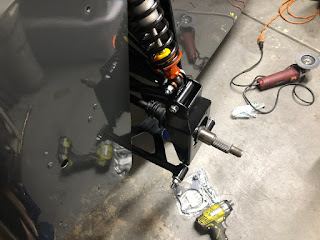
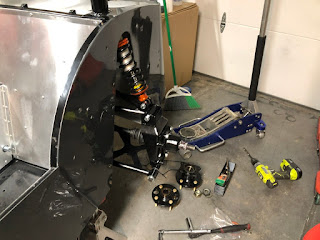
Hub carrier and brake caliper bracket installed.

Saturday, September 26, 2020

Project-Zero: Right rear upper control arm.

It’s only been a FUCKING MONTH since I found out that the right, rear upper control arm on my GBS Zero kit was in no way going to line up and go into it’s home...but it’s on the goddamn car now an barring something really fucky happening it’s not going to have to come off ever again.


It took most of the day to wrestle it onto the car, including a protracted run to the hardware store to pickup up some new, shorter M10x1.50x60 bolts for the upper and lower shock bolts. (For both sides of the car.) The hardware that GBS ships with their ATR shocks is M10.x1.50x70...and those are too long. On the upper mounts they interfere with the frame so you’re not actually able to tight them down snugly.  On the bottom mounts the excessive length isn’t such a problem but since I’m replacing some I might as well replace them all.

My only significant frustrations in this build [so far] have been the horrible quality of the front brake tube nuts and working with GBS to sort out the rear control arm issue. Getting GBS on the phone to talk through the issue was practically impossible. Ultimately the issue was sorted out in a few quick emails but my experience has been that it is almost impossible to get phone support from GBS. (From the US, at least.) I’m honestly deeply disappointed that it took nearly a month to get the control arm issue sorted out. It put a damper on my build enthusiasm with back-of-my head concern that potentially the frame might have had issues.

Monday, September 21, 2020

Project-Zero: Low Pressure Fuel System Plumbing


Started Plumbing the low pressure fuel system.

The feed fuel feel and return lines are 5/16” OD nylon tube in red and black. (red=feed, black=return.) These run from the low pressure filter and pump at the rear of the chassis through the tunnel to swirl pot at the front of the car.  The tunnel has some brackets to help route them cleanly.

The tunnel brackets need to be fitted with grommets to the fuel hoses from rubbing  through. I bought out all of the [5/16”ID, 716” groove diameter, 1/16” groove depth] grommets at my local Outdoor Supply Hardware. These fit into the brackets perfectly and offered a VERY snug fit for the nylon lines.  So snug that nylon fuel lines tended to pull the grommets out of their home while drawing them through.

To solve this, I squeezed a nickel-sized gob of white grease onto a paper towel, then drew the full length of each tube through the greasy towel. I then wiped each tube down again with a clean, dry paper towel.  This left the nylon fuel hoses clean and just slick enough to thread through the tight rubber grommets without pulling out of the chassis in the process.


Thursday, September 17, 2020

Project-Zero: September Parts Drop

The only parts I planned to order this month have arrived.

  • Radium Engineering Ecoboost PCV kit
  • ARP flywheel bolts
  • ARP pressure plate bolts
  • Flyin' Miata clutch/pressure plate kit.
Of note, the Radium Engineering PCV kit is maybe a little unnecessary and overkill. The GBS comes with a PCV blanking plate for the Duratec/MZR engine that I've optioned for my car, it could be modified to suit.

Wednesday, September 16, 2020

Project-Zero: Ignition Barrel Replacement


GBS sent along a new ignition barrel to replace the one that came from the donor steering column. Replacing it is pretty easy if you have the original keys, I didn't.

Barrel removal if you have the original keys:
  1. Insert key into the ignition, turn to position "II".
  2. Press down on the small brass pin with a pick or a punch.
  3. Gently pull & wriggle the barrel out of the steering column.
Barrel removal if you don't have the original keys:
  1. Research "Tibbe lock picking" on Google, watch YouTube videos on the topic.
  2. Order a Tibbe lock picking tool and wait for it to arrive.
  3. Fail to pick the lock with the Tibbe lock picking tool.
  4. Drill out the brass pin with a 5/32" drill bit, then go to town with a hammer and screw driver.
Installing the new barrel:
  1. Insert key into the new barrel, align it so that the key is on "II".
  2. Insert the barrel into the steering column while pressing down on the brass pin.
  3. Have a cocktail.

Monday, September 14, 2020

Project-Zero: Sorting out diff mounting.


Some notes:
  • The installation Order of Operations for the diff are
    • Loosely install lower rear cross-bolt and spacers in the differential.
    • Lift differential in to cat nose/flange first, loosely bolt-in the nose.
    • Lift differential rear, insert the upper rear bolt.
    • Torque everything to spec.
  • Spacers are required:
    • After a little trial and error I found that I need 15mm spacers.

Project-Zero: Proportioning Valve Installed


Future proofing the build a little bit, I've installed a Wilwood proportioning valve between the master cylinder and the rear brakes. This will include a remote adjustment knob somewhere on the dashboard or center console.

In the process of installation I replaced the whole front-to-rear line which I'd completely mangled.  Made a small notch in a body panel for brake line clearance. Installed a 6" strip of clear door edge trim to keep from abrading the remote reservoir supply line to the master cylinder's rear circuit.

Friday, September 11, 2020

Project-Zero: Figured out what was wrong with the right rear suspension.

I've been having some issues getting the right rear suspension put together. The upper and lower control arms just wouldn't line up correctly with the upright. It was a very perplexing issue to encounter but it's getting sorted out now.

I after shooting photos back and forth with Richard at GBS we're pretty sure we know what's going on. First, there's nothing wrong with the mounts on the chassis. That's a huge relief. Second, there's nothing actually wrong with the dimensions of the upper control arm. It turns out I was sent two left upper arms, one of which has an incorrect shock mount bracket denoting it as a right side control arm.

GBS's Ford-style upper rear control arms are the same part left and right, just flipped over with a different shock mount bracket welded on; right-and arms have a notch on the shock mount. Flipping my right-hand arm over proved a notched bracket had been welded to an arm jigged up in left-hand orientation.

I've got a hypothesis for what happened. When GBS produced a set of Ford-style upper rear control arms, a notched shock mount was accidentally welded onto a left-hand arm. After powder coating, the arm was placed into inventory as a right-hand arm because of the notched bracket. It was just dumb luck that the wonky arm was pulled from inventory for my Zero kit.

I'll consider the issue closed as soon as I've got a new actual right-hand arm bolted up to the chassis. (GBS should be shipping it out to me on Monday.)

Wednesday, September 9, 2020

Project-Zero: Brakes, Differential Test Fitment


Brakes/Clutch Plumbing

The brakes and clutch use a common dual-outlet reservoir, which I kind of like. The front/rear brake circuits need to be plumbed into one of the outlets with a T or Y adapter, the clutch master cylinder requires a 7/16" to barb adapter and plumbs into the other reservoir outlet.

I've chosen to plumb the brakes to the side of the reservoir where the fluid level sensor is located.  I also decided that I wasn't happy with the routing required by the use of the GBS supplied 'Y' fitting so I bought a 5/16" nylon T fitting at OSH.

Presently waiting for a proportioning valve to arrive before I commit to remaking the rear brake line. More on that later.

Clutch Fitting

It's not easy finding a 7/16" UNF to 5/16" barb fitting, GBS supplied one in the inventory of parts for my car but I've misplaced it.  I sourced a replacement from Pegasus Racing. They also have a banjo style fitting that I may swap to if the vertical fitting doesn't work as well as I would like. (I don't think that'll be a problem, however.)

Differential

The differential is a 3.6:1 LSD from a Ford Sierra, it fits in the chassis well enough but I'm going to need to fabricate some spacers.  The mounts on the diff case are 7" wide, the chassis brackets are 8.25" wide.  This means I'm going to need 15.5-16mm spacers to center it up in the chassis mount.  I'm going to see if I can get away with printing them in ASA with 100% infill.

Project-Zero: Brake nuts, rear studs.


Front Brakes

I found that the threads of the tube nuts installed on the front brake lines at the GBS workshop were garbage, wouldn't thread on to the GBS supplied ATR braided flexible brake lines. Some other owners have run into the same issue, they've resolved it using an M10x1 tap to clean up the threads. I opted to replace the tube nuts, I was able to steal a good set from a friend's build. 

Rear Brakes

Rear brakes were zero dramas, everything there was fine.

Rear Hub Studs

With the use of a 20-ton press, I installed a set of ARP wheel studs in the Sierra rear hubs. I wanted to use ARP studs to match the style of studs in the front hubs. Turns out that ARP's NA/NB Miata/MX-5 extended wheels as almost a perfect, especially with the use of a 20-ton press.

Wednesday, September 2, 2020

Project-Zero: Steering column is in.

The steering column is in the car, for now. I don't think it's going to need to come out again any time soon. A bunch of tubes of torque seal arrive this week so hopefully I can start torquing things down this weekend.


The sierra column is, in theory, height adjustable but in application for this car might as well not be. In its highest possible position there's only a few millimeters of clearance between the triangular section of the steering column and one of the under-scuttle frame rails.

I've mounted the steering column in place with Class 12.9 M10x1.50x30mm (x2) socket head cap screws and Class 8.8 M10x1.50 nylock nuts.  To help spread out clamping force, I have used 30mm OD M10 washers on front face of the column mounting bracket. These fasteners are absolute over-kill and shouldn't be torqued to more than Class 8.8 M10 threadlock/lubricated spec.

The battery location is great! The Odyssey PC680 fits [almost] perfectly. This battery was damaged in shipping, a new one is on its way. Which reminds me, I should print some terminal protectors.