Monday, October 18, 2021

Project-Zero: Wing/Fender Mounts

I caused a fair bit of irreparable damage to the original front cycle fenders on the car.  I ordered a set in black gel coat GRP from Kit Cars Direct as a quick replacement.  I'm not super thrilled with them but they'll work.

To mount them to the car, I'm using M6x1.0 bond-in studs and 3D printed (PETG) saddles that will clamp over the fender stays.  To bond the studs to the underside of the fenders I'm using polyurethane adhesive that came with the GBS Zero kit that I have not yet used anywhere else in the car.

UPDATE: This process has worked well except that the Alpha 123 PU Sealant is stupid and you shouldn't use it for this application.  What you should use is 3M 3815 panel bonding adhesive...It's the stuff they use to glue McLarens together.   Also, you should use bond-in studs with larger base.  I've updated the materials section.

Materials:

  1. M6x1.0x12mm bond-in studs - https://www.mcmaster.com/97590A881/
  2. 3M 3815 Panel Bonding Adhesive - https://www.amazon.com/dp/B00596RP8A/ref=cm_sw_r_tw_dp_1QWN42PXAFB18251X21R

Process:

  1. To place the fenders, I used a digital angle finder to level out the fenders before sketching out the locations where I wanted the saddles to sit with a gold Sharpie marker.
  2. Then I squeezed sealant/adhesive on the backs of the bond in studs before smooshing them into place on the inside of the fenders.
  3. Using nitrile gloves and a little bit of rubbing alcohol, I smoothed the adhesive over and around the base of the studs.
  4. Allowed to cure for 24 hours before mounting the fenders.
  5. The poly sealant has a sheer strength of about 7lb/ft.  That's fine, you really shouldn't need to torque very tightly anyway. (Torqe to 5-6lb/ft or 60-70lb/in of force)


Project-Zero: Wiper Arm Modification

NOTE: I am not using these wiper arms.  Instead I bought a better set from an outfit in the UK.

The wiper arms that shipped with my GBS Zero kit were way too long and needed to be modified. The first go at this I just cut the blade to fit but that was...not good.

The second go, I drilled out the rivets holding the wiper arm together, marked the length needed for the the blade fit the windscreen at the highest point in its sweep.  Marked it up, then drilled the arm. Before I riveted the arm back together, I made the same mod to the other wiper arm using the first as template so that they're the identical length.

Before and after pic.


Thursday, October 7, 2021

Project-Zero: Charge Warning Lamp Circuit

 Not that long ago I built an alternator exciter/charge warning indicator for the Zero.  I thought I would follow that up a bit.

The idea is that you want to have a way to 1) excite the alternator field so that it actually charges at idle and 2) have something that will tell you when the alternator is putting out less juice than it should be.

The circuit itself is very simple and has been used in cars since the invention of alternators.  basically, you you create a circuit with a diode and a resistance load that connects the positive terminal of the battery with the positive output of the alternator.

If the forward voltage from the alternator is greater than the forward voltage from the battery, the diode will force current to flow through the nominal load of the resistor and prevent the lamp/led from illuminating. 

If the forward voltage from the battery is greater than the voltage from the alternator, current will flow through the diode thus illuminate the warning signal.


My particular circuit uses an LED because...well...the circuit required a diode so why shouldn't it do double duty?  You can make the exact same circuit using an incandescent bulb but...why?  Anyway, I've included diagrams of an incandescent version of the same below.


Wednesday, October 6, 2021

Project-Zero: Steering Wheel stuff.

 After spending a good amount of time in the car last week doing the CHP inspection/VIN assignment thing I've decided that I need to revisit the steering wheel on my Zero a bit.

  • The hub adapter and quick release adapter length is ridiculously long and not really all that comfortable to use. 
  • The steering wheel feels a little too small for my liking.

The quick release is ~2.5 inches long, the hub is ~3.3 inches long.  It's just...dumb.

For now, I'm deleting the quick release. In the future I'll modify the steering wheel hub adapter (cut off the crash structure, drill and tap bolt holes) and maybe swap to a thin quick release adapter. (https://getnrg.com/collections/quick-releases/products/srk-400)

As for the wheel, I've swapped in my spare NRG 320mm steering wheel to see if I like it any more than the 300mm MOMO wheel.

Friday, September 24, 2021

Project-Zero: Bosch TMAP ( P/N: 0 261 230 044 ) pinouts

Because I couldn't find particularly good information on this sensor I went down a few wrong paths while troubleshooting an issue that I was having with it. For that reason, I'm making this post so that FutureMe will have this information that PresentMe is sure to forget in very short order.

If you find this information useful, GREAT! But also know that it not derived from any official sources so your mileage may vary and I'm not responsible if you break your sensor, your car, or burn your house down while trying to get your TMAP sensor working.


Temperature Calibration Table

This calibration table is for the Bosch NTC type thermistor. These values seem to be accurate for this sensor but are not taken directly from any form of documentation regarding this specific part number because I can't find documentation about this specific part number.

Bosch NTC
OhmsOutput V
45,3134.89
26,1144.82
15,4624.70
9,3974.52
5,8964.27
3,7923.96
2,5003.57
20573.36
1,7073.15
1,1752.70
8342.27
5961.87
4361.52
3231.22
2430.98
1870.79
1440.63
1130.51
890.41

Pressure Calibration

This pressure calibration is a wild-ass guess. Don't use.  If I find more information I'll add it. (This assumes that this is a 4-bar MAP, which I don't think it is.  I think it's probaby a 1-2 bar MAP sensor but I haven't been able to confirm that yet.)

Pressure
V outBarPSI
0.38600
4.5458

Monday, September 20, 2021

Project-Zero: Intake Air Temperature Issues

Problem

While zipping around in the Zero for inspections I noticed that the intake air temperature appears to be stuck at 104˚f (40˚c) with zero fluctuation.  The car is drivable but it's not an ideal situation as the ECU may adjust fueling to account for temperatures.

Investigation

Connecting up to Emerald K6 ECU confirmed the ECU deferred to the default IAT value, 40˚c and a sensor fault.

  • To verify the ECU was fine I wired in a Delphi sensor/calibration.
    • Returned 78˚f with no faults. (Ambient for the evening in my garage)
  • Swapped pins around for the FoMoCo TMAP. <=== THIS WAS NOT THE PROBLEM.
    • No ECU faults but a very incorrect temperature (127.4˚f).
    • I suspect that the TMAP is broken. <=== THIS WAS THE PROBLEM.

In the process of swapping pins I went a little too hard and snapped one of the pin catches off which will require a replacement.

Next Steps

  • Plan A) (Plan A was the solution)
    • Replace the broken connector housing.
    • Replace the [potentially] broken TMAP.
      • Replacements have been sourced from RockAuto.
  • Plan B) (Plan B was not needed.)
    • Roll forward with the GM IAT sensor and source a GM 3-bar MAP sensor.
      • Split the sensor ground.
      • Has the advantage that I would absolutely know the calibration values for each sensor.

Notes

Sunday, September 12, 2021

Project-Zero: ETB Fuel Level Sender and Gauge

 The Zero has been on stands for a few weeks while I work on small things.  Last time I updated here I was working on calibrating the Smiths fuel level sender to work with the AIM dash.

That didn’t go well.

Eventually I’ll revisit the notion of having the AIM display fuel level but for now I’m throwing an ETB Instruments sender and GT40 style gauge into a 3D printed pod sticky-taped to the dash. I went with ETB because their sender fit the bolt battery GBS use on their tank so it was easy.

The lever arm of the sender needed to be adjusted for length to keep it from hitting the sides or bottom of the tank. (There’s about 3/4” between the bottom of the float and tank at full droop.) This provides a bit of a buffer at ‘E’ which is good since the car’s tank realistically only holds 7.5 US gallons of fuel.

The gauge is wired to the send through the factory harness, not the AIM harness I built.  For simplicity I’m taking switched power and ground from the USB charger/voltmeter in the center console. The gauge pod is my own design that uses GoPro mounting hardware and 3M mounting tape to stick to the underside of the carbon fiber dashboard.  I didn’t bother wiring up the gauge illumination.

Anyway, I now have a working fuel level gauge which is honestly all that I care about while working out confidence in what kind of range I’m going to be able to get out of this car.


Thursday, August 26, 2021

Project-Zero: Fuel Level Wonkiness

My first try at calibrating the fuel level sender in my car did not go well.

My calibration process kind of sucked, I can do much better. I spilled fuel, it wasn't a clean way to do thing. The next go of it I'll actually have a 1 gallon fuel jug and no-slosh funnel.

Not really happy with the fuel level sender I was gifted by a friend, I ordered a new sender/gauge kit from ETB Instruments in the UK. It gives me a known good starting point.

The new sensor should read:

  • 260 ohms, empty ( 0.631v w/ 1.8K ohm pull-up )
  • 20 ohms, full ( 0.055v w/ 1.8K ohm pull-up )

Which the simulations on EveryCircuit confirm.

GBS Zero Fuel Level Sender - EveryCircuit


Tuesday, August 10, 2021

Project-Zero: Paint Codes

For future reference, the paint on my Zero is:

Body: Lamborghini Grigio Telesto Metallic (6Z6Z - Battleship Gray Metallic, essentially.)

Stripes: Luminous Green (RAL 6038)

Tuesday, May 18, 2021

Project-Zero: Fitting the AIM MSX & pilot lights in the carbon fibre dash .


Spent a little bit of time after work last night offering up the AIM MXS dash to the carbon fibre dashboard. Also, the dash lights. (Was going to do something fancy for those, turns out I didn't care enough and just set them straight into the dash.)  To make sure that holes were [mostly] in the right place I drew up a couple of templates with Fusion 360 and kicked them out on my Ender3 Printer. (I mostly use my 3D printer to knock out single use tooling, like this.)

I'm happy enough with the end result of the work even though it's a bit of a horror show where I cut out the 2" rounds to fit the back protrusion of the dashboard. Doesn't matter, tho, that's covered by the dash itself.  And one of the dash lights is slight offset which will forever be a tiny annoyance.

Saturday, May 15, 2021

Project-Zero: Emerald K6 Configuration Stuff

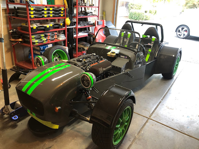
Ran into some issues trying to finally get the engine to turn over that turned out to be an ECU configuration problem that was partially user error and partially some questionable choices made by Emerald M3D on how they package and sell their ECUs.

The Issue

When attempting to crank the engine over it wouldn't catch or run.  Probing with a multimeter revealed that fuel rail and coils weren't getting power, ECU logs also suggested that the ECU wasn't getting power to its second 12V in, either.  

The Problem

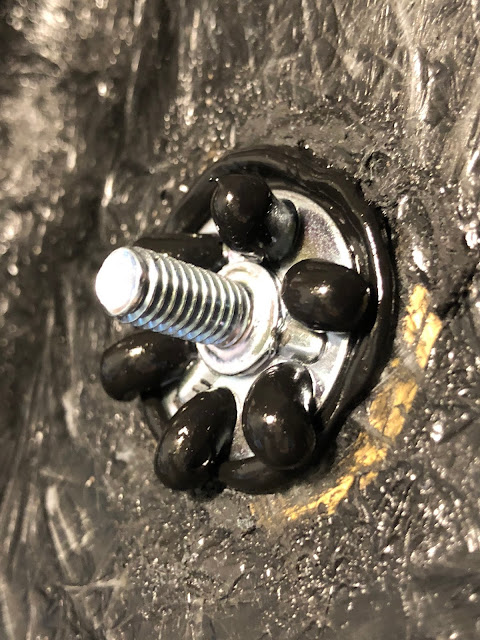
While it was pretty clear that the issue was that the ECU wasn't triggering the Main Relay to supply the injectors, ignition, or the ECU with battery volts, figuring out why was a bigger pain in the butt than it should have been.  I traced the Main relay back to pin 14 on the ECU which all of the documentation I could find on the K6 ECU lists as supplying +8v for sensors, not switching ground.  Weird but workable...except that the GBS harness is wired for the ECU to switch pin 14 to ground, not to supply 8v. 

I thought I might have to rewire the chassis harness to so the Main Relay would be triggered by a positive source from the ECU or that I might need to move the ECU pin to a different port.  But I couldn't find any option at all in the configuration software to actually set where the main relay is triggered from.  The documentation seemed to suggest that it would be triggered from Pin 4 as long as Pin 4 wasn't configured as an ignition driver but offered no alternatives.  And pin 4 on my setup is an ignition driver.

To make what could be a very long story short, I got in touch with Emerald and quickly discovered two problems:
  • I had the wrong version of Emerald's ECU software installed.
    • I downloaded the config software from Emerald's web site, I don't own any computers with  DVD drives that could have read/loaded the software that was in the included DVD drive.
    • I made the incorrect assumption that would be be the most complete, up-to-date version. It was not.
    • Some K6 ECUs require bespoke software versions, my K6 VVT was not 100% compatible with the software version on their website.
  • Emerald's documentation is is kinda crap.
    • The K6 documentation lists pin 14 as a +8v sensor. Emerald's support rep told me that pin 14 on the K6 VVT ECU is actually a configurable spare output.
    • Every single bit of documentation for the K6 ECU on both their website and on the DVD included with the ECU fails to actually correctly capture and convey all of the actual inputs and outputs of the ECU that I was shipped.

The Solution

  • Installed the correct version of the software.
    • Emerald's support emailed me the correct version of the configuration software for my specific ECU.
    • Seriously, who creates bespoke versions of configuration software like that?!?!
  • Set Pin 14 to control the main relay.
    • Changed the Main Relay trigger from Pin 4 to Pin 14.
    • Verified that the VVT solenoid had was configured to trigger on Pin 3 instead of Pin 17. (Old issue I found while sorting out the wiring harness.)

The Take Away

I was bitten by the very reasonable assumption that the software available on Emerald's site would be the most current version and would be able to configure all versions of the K6 ECU that they ship to customers.  Shipping bespoke versions of software for specific versions of an ECU is kinda crap.  I have to be careful now not to lose the installer.  It's also very likely because of the bespoke nature of both the ECU and the configuration software that there will NEVER be firmware or software updates for my specific K6 ECU or the configuration software needed to make it work.

It also means that when I take the car in to be tuned I'm going to have to make sure that my tuner has the special, bespoke version of the tuning software on his laptop.

Those aren't show-stopping issues but they are annoying.

However, the car stared right up and just ran after finally getting the ECU outputs correctly matching the reality of the chassis and engine harness configuration so that's not annoying.

In the future I may change the car over to a different ECU, maybe Megasquirt or Haltech, but for now I'm gonna go with what I got 'cause it runs.

Project-Zero: Fluids are filled.

 It's been a bit of time since I've made an update here and it's time to do some brain dumping, starting with some fluids.

The car is now presently full of fluids. Let's talk about them.

  • Engine Oil
    • Motorcraft 5W-20 full synthetic - No point in using anything more exotic, special, or expensive on the car right now.
  • Transmission fluid
    • Redline MTL Gear Oil - 75W-80 GL-4 gear oil, pretty much the only thing that I use in my Miata transmissions.
  • Gear Oil
    • Royal Purple Max Gear - 75w-90. I needed 75W-90 for the differential and this is what Winchester Auto had in stock. I would have preferred Redline but in a pandemic, beggars can't be choosers.
  • Coolant
    • Distilled Water & [water wetter] - I live in California, there's no real need to run anti-freeze.  Distilled water and some anti-corrosive additives are good.
  • Brake Fluid
    • Generic DOT-4 - Again, nothing special right now.  High enough temp resistance and fairly inexpensive.  I really don't like the idea of leaking Ate or Motul all over the garage while hunting down leaks.  I can bleed it all out later, if needed.

Wednesday, March 3, 2021

Project-Zero: Flasher Relay Redux

 The LED flasher that I bought was garbage, I updated my previous post with that information.  I've replaced it with a more expensive electronic flasher that shouldn't suffer from the terrible electro mechanical issues the one I first bought has.

The new LED Flasher (FL3-RED-K) is a three pin flasher but the GBS Zero's flasher socket will need to be re-pinned. The short story is that the GBS is pinned for ISO relays, FL3-RED-K relay that I purchased is pinned as a JSO relay. Research into that what you will but the following diagram should help on that.

Basically, looking at the back of the Relay Socket everything needs to rotate one tab clockwise.


Monday, March 1, 2021

Project-Zero: Oil Pressure Switch Problems

I have learned through trial and error that the oil pressure switch use in the Ford Fusion that my engine came from is not compatible with the way that the GBS us wired up.

UPDATE: I chose Solution 1 however that introduced another issue that required me to swap out the switch connector housing. Making a long story short, you want a WVE Vehicle Electronics 1P1883 connector pig-tail kit. De-pin/swap connectors or cut and splice, whichever method floats your boat. (I de-pinned 'cause that's how I roll.)

The Problem

The Ford switch from the fusion is wired to be normally open, meaning that when it sees no oil pressure the switch is open and the GBS Zero's indicator light will be off. When there is oil pressure the switch will close and illuminate the warning light. Neither of the conditions is desirable.

The Solution

Find an oil pressure switch thats normally closed. I present three options here.

  1. Standard Motor Products PS299 - Inexpensive, should fit in the ATR oil filter housing without needing to us any adapters, appears to have the same dimensions as the Ford Fusion's pressure sensor, just NC instead of NO. Yay!
  2. MOTORCRAFT SW5029 - Inexpensive, used in millions of Ford cars. Should fit in the ATR oil filter housing.
  3. ACDelco 8020 - Opens at 5psi, inexpensive, used on millions of cars since the 1960's. Doesn't fit in the ATR oil filter housing because hexagonal body is just a bit too large. You would need to mount this in a remote location.

Friday, February 26, 2021

Project-Zero: Warning Indicators

The Short Story

I'm going to go with the Summit Technologies HAWK Array rather than rolling my own. It's less expensive and would look better than what I would build for my own usage.

NOTE: This is a lie, I wound up rolling my own anyway.

The Less Short Story

For the purpose of testing my car's electrics I built a prototype indicator array. It half worked. I sunk all of the LED cathodes to a common chassis ground because I made bad assumptions. 

What indicators sink to what, briefly.

  • Discrete Source, Common Sink
    • Right Turn
    • Left Turn
    • High Beam
  • Common Source, Discrete Sink
    • Oil Pressure
    • Alternator
    • Brake

分りません!

Reading it that way is a little confusing if you've not fully grasped that some things within the car are ground switched. I had the boys down in R&D whip up this janky diagram to help better illustrate the point. (Brown lines are ground/sinks)

How does the HAWK Array work in this configuration?

The HAWK indicator array is already wired up with exactly these indicators lamps with exactly this configuration of sources and sinks. It's like it was purpose built for British kit cars. (It was purpose built for British kit cars.)

What the other stuff about bulbs, watts, and field exciter circuits?

Depending, I may need to build a circuit that will excite the alternator so that it'll produce power at idle. It's a fairly simple circuit, especially if you're using an incandescent bulb. If you're using an LED, well, they offer little forward resistance so they might not excite the alternator and you need to bridge a resistor that will simulate the load of a 2-4 watt bulb. (@12V)  I might need to do this with the HAWK array, but I'm not 100% sure on that right now.

Thursday, February 25, 2021

Project-Zero: Oiling System

I've gone back and forth on the cooling system on my car for a bit but I've come up with a solution that I like and am presently implementing.


The Problem:

The location of the engine and oil filter in the engine bay of a GBS Zero with a Ford Duratec engine sucks. A lot.  The filter sits on its side over an area where it will make an unholy mess when it's time to change the oil filter.  The problem is even worse if you're running with GBS' supplied oil cooler kit.

Exhibit A:


(The oil filter hangs out over a fuel line and some of the body work that would love to collect and trap some oil dripping out of the filter when it gets removed.)

The Solution:

The easy to say answer is "Install a remote oil filter mount." On the Generation 2 chassis, that's not as easy as it seems but I've managed to make it work out. The only down side of my solution to this problem is that I lose the oil thermostat so it will take a little longer for the care to come up to full temperature. Not much of a problem, to be completely honest.

  • Location - In a Generation 2 GBS Zero chassis locations for a remote mount oil filter are limited. In my car, the best place is beside the battery on the passenger's side.
  • Remote Oil Filter Mount - I sourced a used CV Products remote oil filter mount from Ebay. (-10AN inlet/outlet ports, 1/8 npt port (post filter), 3/4-16 oil filter nipple) This mount features angled inlets ports opposite from each other and outlet on top.
  • Oil Filter Takeoff/Bypass - I am using the oil cooler takeoff sandwich provided by GBS and a filter bypass plate from Torques.co.uk. (Purchased on Ebay) In the future I might change to one of Mountune's oil takeoff plates but this setup should work for now.
  • Mounting Bracket - I built a simple, robust mount out of 1.25" (.125" thick) angle iron. It mounts to the chassis rail with some M6 rivnuts. (See the video.)

Exhibit B:


Foot Notes:

1. The reason that I have to lose the thermostat is that with the thermostat in place, unfiltered oil would be circulated through the engine until it gets to 180˚f and the thermostat closes. No bueno.

Tuesday, February 23, 2021

Project-Zero: Direct Fit Oil Filter Cross Reference

The following is a table of oil filters that should be direct fit swaps for my Zero. 

For future reference, the Motorcraft FL910S is about an inch longer than the supplied BluePrint  oil filter, I'll probably just use those going forward for that touch extra capacity.

Direct Fit (Per Rock Auto)Extra NotationsNotes
Ford/MotorcraftFL910S
WIX51348XP
Fram3614XG/FS/FF/TG/PH
K&Nhp-1002
Bosch3330
Denso1502010
MazdaLF0514302A
MazdaLF0514302B

Thursday, February 18, 2021

Project-Zero: GBSゼロ - First Power

Project-Zero: LEDs and flasher relay

UPDATE (03/03/2021):

The flasher that I bought is complete and utter garbage. Do not buy it. It will kill your children, corrupt your dog, and run off with your spouse on a bank robbery spree.

Another thing to think about, the GBS Zero uses ISO standard pin outs for the flasher relay.

You can easily use Grote 44892 LED flasher unit.

LEDs and Flasher Relay 

GBS included a flasher relay intended for incandescent bulbs however they shipped LED front turn signals and incandescent tail/brake/rear-turn bulbs with the car.  This will result in a fast than desired flashing of the right and left turn signals. The quick solution is to just replace all of the remaining indicator bulbs with LEDs and flasher relay. (With an LED compatible relay)  While I'm at it, I've also purchased a set of LED H4 headlights.

I bought all of the needed parts at SuperBrightLEDs.com, part numbers are below.

  • Brake/Tail (red) - 1157 Socket x2 - 1157-R27-T-2PK
  • Rear Fog (red) - 1156 Socket x1 - 1156-R27-T
  • Reverse Light (white) - 1156 Socket x 1 - 1156-NW27-T
  • Turn Indicator (amber) - 1156 Socket x2 - 1156-A27-T-2PK
  • LED Flasher Relay - CF13GL-02 FL3-RED-K
  • H4 Headlights - H4-HLV7

Wednesday, February 10, 2021

Project-Zero: Oil Pressure Sensor Wiring

AIM do make a 0-150PSI pressure sensor with an integrated Binder 719 connector, it's expensive. I have several spare functionally identical Packard/Delphi sensors laying around from past projects and a small handful of 719 connectors. The preference is to use what I have on hand that sets me up for less expensive replacement costs in the future, should the sensor crap itself. (Pressure transducers are a little delicate, they don't like a lot of heat and vibrations.)

This is the wiring/soldering game plan to connect up the “generic” Packard sensors to the AIM MSX dash that I’m using. Nothing too special, just a distillation of information from a couple of different sources to help keep me from jacking things up too bad. 


The Binder 719’s on the the MXS’s harness are of the 4-pin variety.  When looking at them from solder termination side, index tab pointed upward, the pins can be read as:

719 Male - From solder termination side

  1. Upper Right - Analog Signal
  2. Lower Right - Sensor Ground
  3. Lower Left - +12V (Battery)
  4. Upper Left - +5v (Sensor Vref)
719 Female - From solder termination side
  1. Upper Left - Analog Signal
  2. Lower Left - Sensor Ground
  3. Lower Right - +12v (Battery)
  4. Upper Right - +5v (Sensor Vref)
Packard/Delphi 3-pin Transducer - Looking at the pins on the sensor side
  1. Lower Center - Analog Signal
  2. Upper Right - +5v (Sensor Vref)
  3. Upper Left - Sensor Ground
Connecting up the +12V pin on the Binder connectors is no bueno.

Tuesday, February 9, 2021

Project-Zero: ECU Mount

Originally I thought I might put the ECU on top of the transmission tunnel behind the aux switch panel but have since come to a different opinion on placement.  Instead I’m flying it on the passenger’s side of the scuttle/dash area mounted to a plywood tray/shelf.

The shelf is a piece of 1/8" plywood mounted with a few 3D printed brackets. (PETG) The plywood was a 1’x1’ sheet sourced from the local hardware store, fit into place and then cut down as needed.  It has ended up as a kind of funky shape but it works and finished off with some black paint it doesn’t even look that weird.


Monday, February 8, 2021

Project-Zero: Fuel Level Sender to AIM Cable Build

I ordered the Zero without instrumentation, I'm using an AIM MXS. Fuel level will go to the MXS as an analog input.

This requires a cable with a pull-up resistor between +5v and the signal. (AIM have a good description of it in this PDF.)

I used a 1.8K ohm resistor for the pull-up.

Monday, January 18, 2021

Project-Zero: January Update

 Not a whole lot more progress but this is where we're at:

  • PCV/Catch Can System - This has all been plumbed in now.  Relatively inexpensive catch can from Amazon, fitted with three brass barbs I sourced at a local hardware store.  Being three port in this situation is super important since I need to plumb the breather and PCV systems into the intake. This is all plumbed with low pressure emissions/fuel hose.  Both PCV and Breather are plumbed into the in-ports on the catch can, then from the out-port into the injector-plug ports that have been lightly tapped into the cylinder head in place of the stock injectors.
  • Alternator - Finally got the alternator bracket I needed from GBS so the alternator is in. In my application, I needed to find a belt that would fit correctly. I went through a couple of iterations on this, the end result is a K040570 (4PK1450) Gates Micro-V belt.
  • VVT Solenoid Connectors - While swapping the VVT solenoid connector, I probed out the connections and found the wiring harness/ECU info sheet disagree.  The documentation says that the VVT solenoid is wired on pin 17. This is a lie. There's nothing at all wired on pin 17 in my ECU harness. The connector labeled "VVT Solenoid" is really wired to pin 3 which the docs lists as the Idle Air Control Valve solenoid. I will need to keep this in mind.
  • QuickJacks - I bought a second hand set of 12V powered QuickJacks. I've used them to put the car up in the air and even with just this single use it has been amazing. I don't know how I've gone so long without these, expect some upgrades this system to come along in the future.
  • Fuel Pump Fuckery - The high pressure fuel pump on the car has male FASTON terminals, one is .25" (ground) and the other is .312" wide. (+12v) The harness only has .25" female FASTON terminals for the pump. This is less than useful and I've had to order a hand full of female FASTON connectors from Digi-Key.
  • Nylon Spacers - I bought a chunk of delrin from McMaster with which to make some replacement spaces for the differential.  I should have used nylon from the start instead of aluminum. Used the bandsaw and drill press for this, really wish I had a lathe for this operation but managed to get everything done and back into the car with only a small amount of cursing.